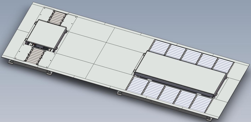
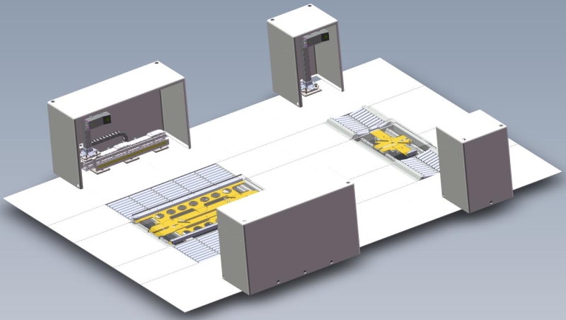
The IEL series centering device (aligner) is used to align the test vehicle parked at the inspection station, so that the longitudinal center line of the vehicle is aligned with the equipment.
The sensor adopts laser based on the triangulation principle for measurement. The position of the linear laser inside the sensor and the angle with the camera are calibrated, and the parameters are fixed. A 635nm red laser vertically irradiates the highest point of the wheel arch on the front axle plane, which is imaged and recognized by the 2D camera on the CCD. The software calculates the inflection point of the laser line, and solves the Y and Z coordinates of the inflection point according to the laser triangulation principle, where the Z coordinate is the wheel arch height.
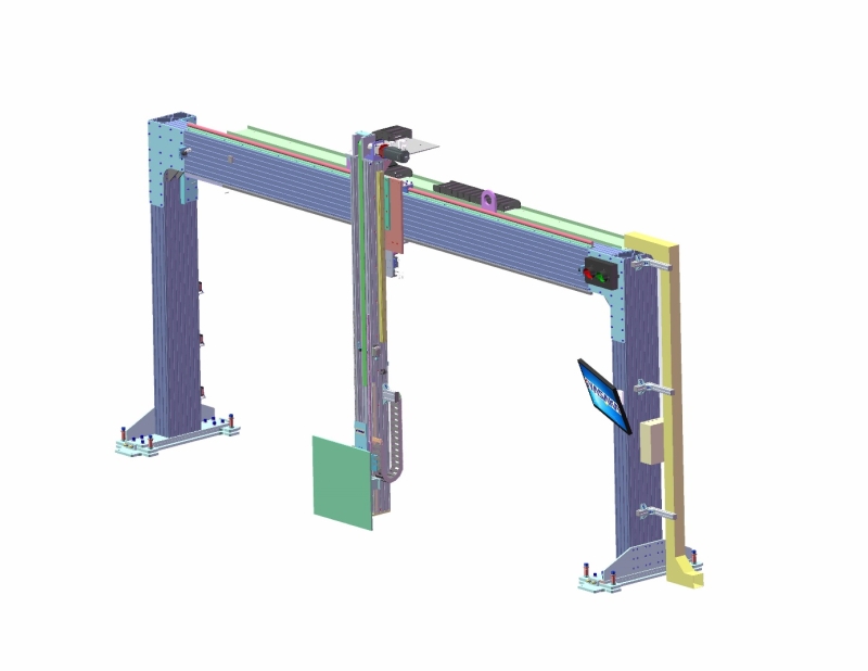
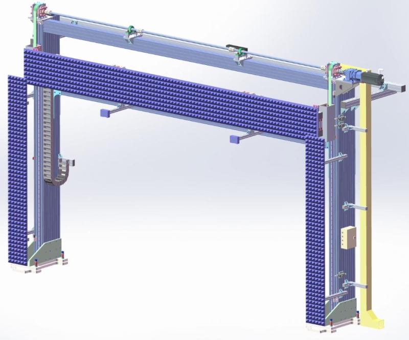
An aluminum alloy gantry structure is adopted to support the ACC calibration target board. In the Y-axis direction, it is equipped with Siemens servo motors and cylindrical slide rails, and the automatic movement adopts a servo-driven rack transmission method. In the Z-axis direction, it is equipped with Siemens servo motors and linear slide rails, and the automatic movement adopts a servo-driven synchronous belt transmission method with precise positioning. The Y-axis movement speed is greater than 250mm/s, and the Z-axis movement speed is greater than 150mm/s.
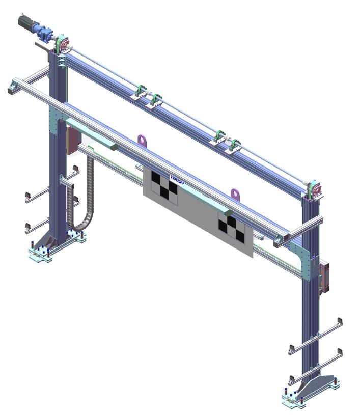
An aluminum alloy gantry structure is used to support the LDW calibration target board. A Siemens servo motor and linear slide rail are equipped in the Z direction. The target board adopts a servo-driven synchronous belt transmission method for movement in the Z direction, achieving precise positioning, with a Z-direction movement speed greater than 150mm/s.
An aluminum alloy gantry structure is used to support the BSD reflective triangular cone. A Siemens servo motor and linear slide rail are equipped in the X-axis direction, with automatic movement realized by a synchronous servo-driven synchronous belt transmission method. A Siemens servo motor and cylindrical slide rail are equipped in the Y-axis direction, with automatic movement adopted by a servo-driven gear and rack transmission method. A Siemens servo motor and linear slide rail are equipped in the Z direction, with automatic movement achieved by a synchronous servo-driven synchronous belt transmission method, and precise positioning is realized. The X-direction movement speed is greater than 150mm/s, the Y-direction movement speed is greater than 250mm/s, and the Z-direction movement speed is not greater than 150mm/s.
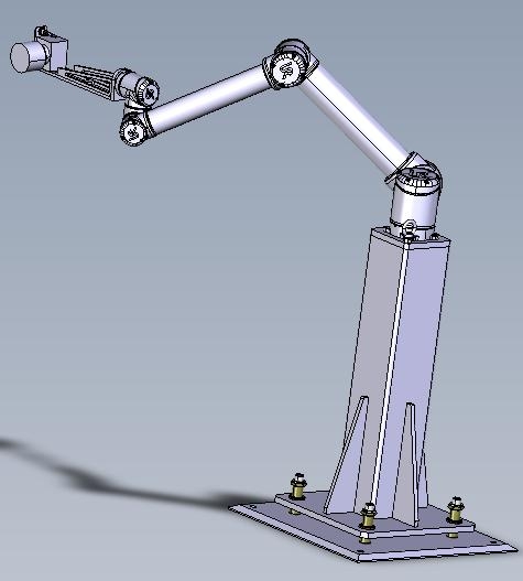
A 6-axis collaborative robot is used to move the camera in a fully automatic manner, eliminating the need for operators to provide auxiliary movement operations. When the robot is not working, the entire robot automatically moves to a position away from the driver's seat to facilitate the driver's getting off the vehicle.