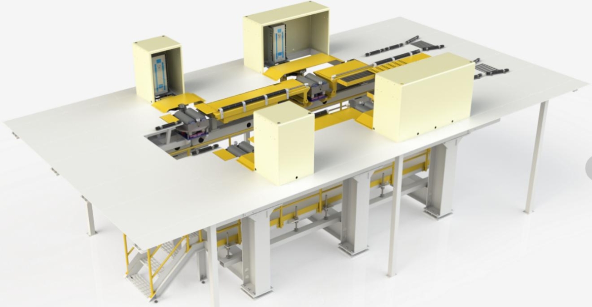
Product Details
Overview
The four-wheel aligner is used to detect and adjust chassis parameters such as toe-in, camber, and steering angle of wheels, ensuring the consistency of the vehicle chassis state.
The WAT-2500 series 3D laser four-wheel aligner is used to measure the toe-in and camber of the wheel alignment of assembled vehicles, ensuring that the wheel alignment meets the design parameters and requirements. By adjusting the toe-in or camber, the straight-line driving ability of the vehicle is guaranteed.
The 3D laser sensor of the four-wheel aligner adopts the imaging processing technology of dynamic multi-line laser irradiation and reconstructs the 3D model of the tire to measure the toe-in and camber. It has the characteristics of high measurement accuracy, small repeatability error and stable operation.
Measurement Content
1. Toe-in Measurement and Adjustment
1.1 Automatically measure and display the front wheel toe-in (left/right wheel) in real time, adjusted manually by the operator;
1.2 Automatically measure and display the rear wheel toe-in (left/right wheel) in real time, adjusted manually by the operator;
1.3 Automatically calculate and display the total toe-in value of the front axle, rear axle and the thrust angle in real time;
1.4 The adjustment of front wheel toe-in shall take the rear axle thrust angle as compensation.
2. Camber Measurement and Adjustment
2.1 Automatically measure and display the front wheel camber (left/right wheel) in real time, only measure without adjustment or optional manual adjustment;
2.2 Automatically measure and display the rear wheel camber (left/right wheel) in real time, only measure without adjustment or optional manual adjustment;
2.3 Automatically calculate and display the total front wheel camber in real time;
2.4 Automatically calculate and display the total rear wheel camber in real time.
3. Caster Angle of Front Wheels
Measured by the swing method, only measurement without adjustment.
4. Kingpin Inclination Angle of Front Wheels
Measured by the swing method, only measurement without adjustment.
5. Maximum Steering Angle
Maximum steering angle of left and right wheels.
6. Vehicle Body (Fender) Height Measurement (Optional)
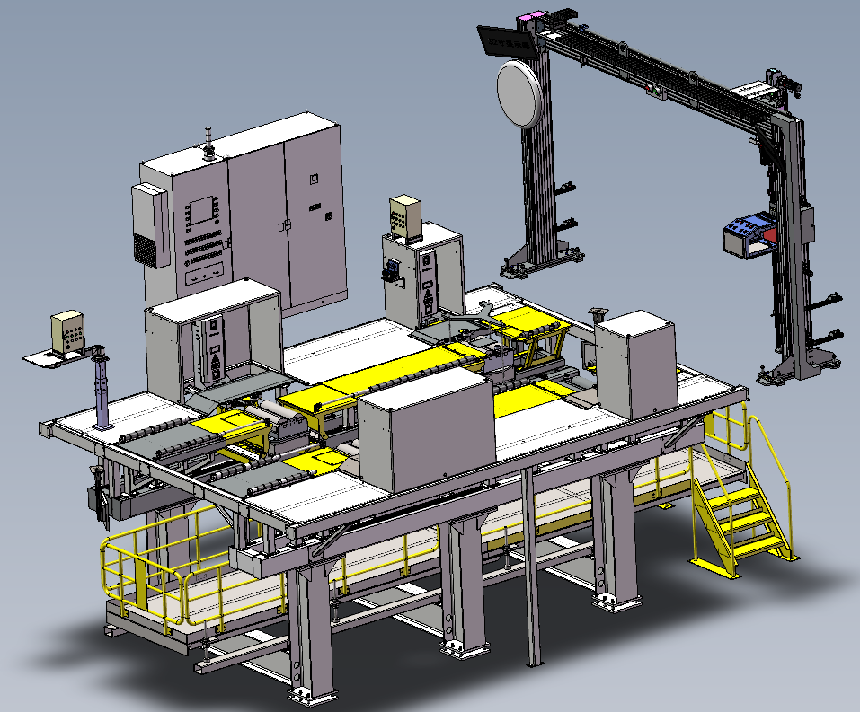
Measurement Range and Accuracy
Item | Measurement Range | Accuracy | Repeatability Accuracy | Remarks |
Toe-in | ±10° | ±1’ | ±0.2’ | Mandatory Inspection Item |
Camber | ±10° | ±2’ | ±0.4’ | Mandatory Inspection Item |
Caster | ±15° | - | ±0.2° | Random Inspection Item |
Kingpin | ±20° | - | ±4° | Random Inspection Item |
Steering Angle | ±50° | ±0.5° | ±0.5° | Random Inspection Item |
Fender Height | - | ±1mm | ±0.2mm | Optional Item |
Testing Principle
Adopting the independently developed 3D laser sensor, multi-line laser projects on the outer surface of the tire. The binocular 3D vision sensor (camera) captures the images of the multi-line structured light on the tire surface at the same time. The 3D point cloud data of the wheel side is obtained through stereo vision algorithm processing. The toe-in and camber are measured by a specific evaluation and measurement algorithm, and the caster angle and kingpin inclination angle can be calculated through the swing method test.
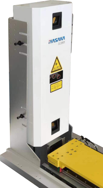
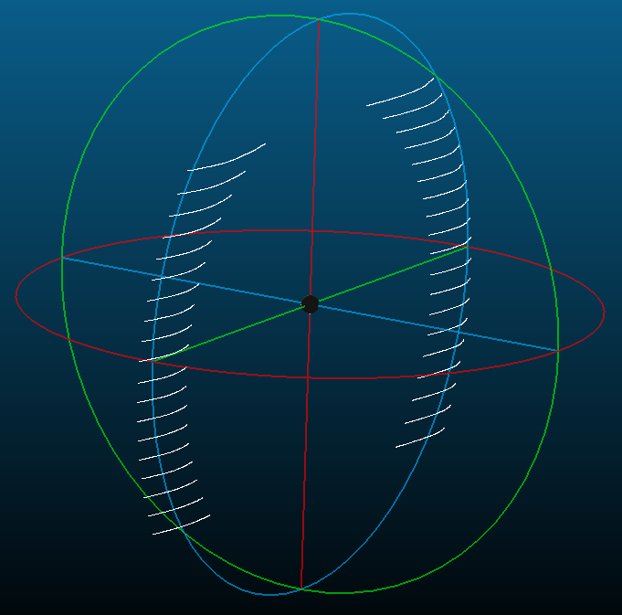
3D Laser Sensor 3D Point Cloud Data
On-site Installation and Use
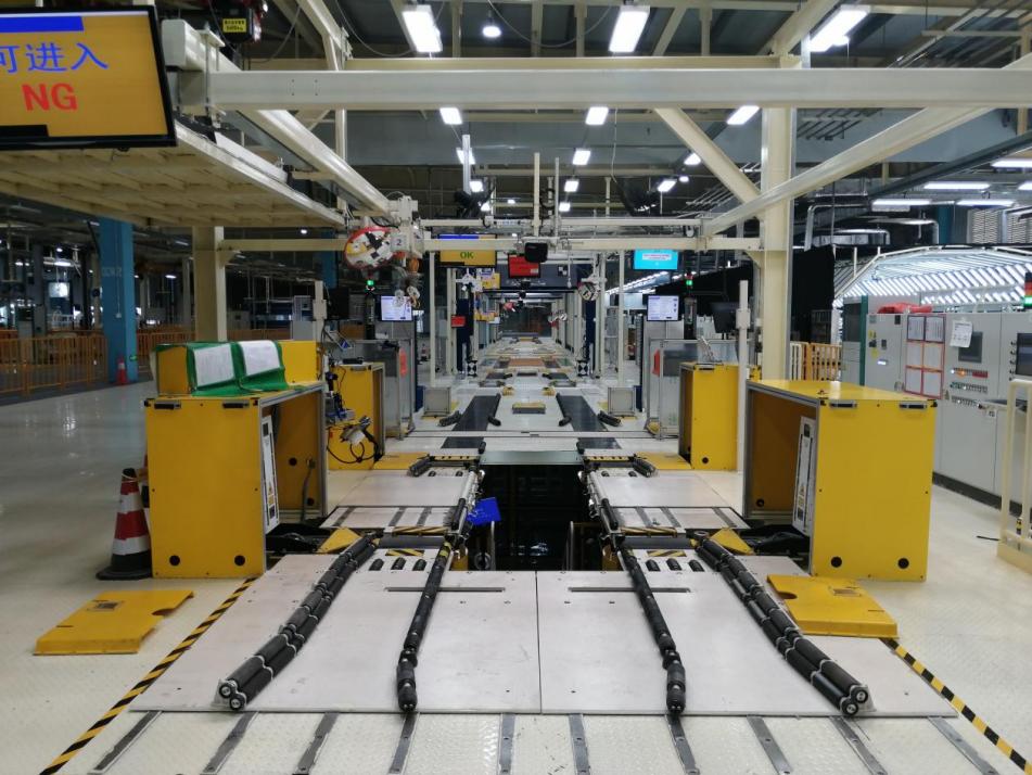
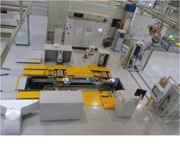
Back