Product Details
Overview
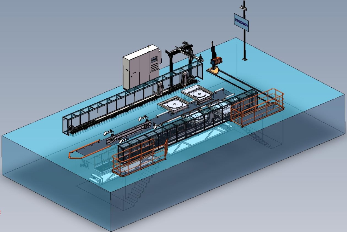
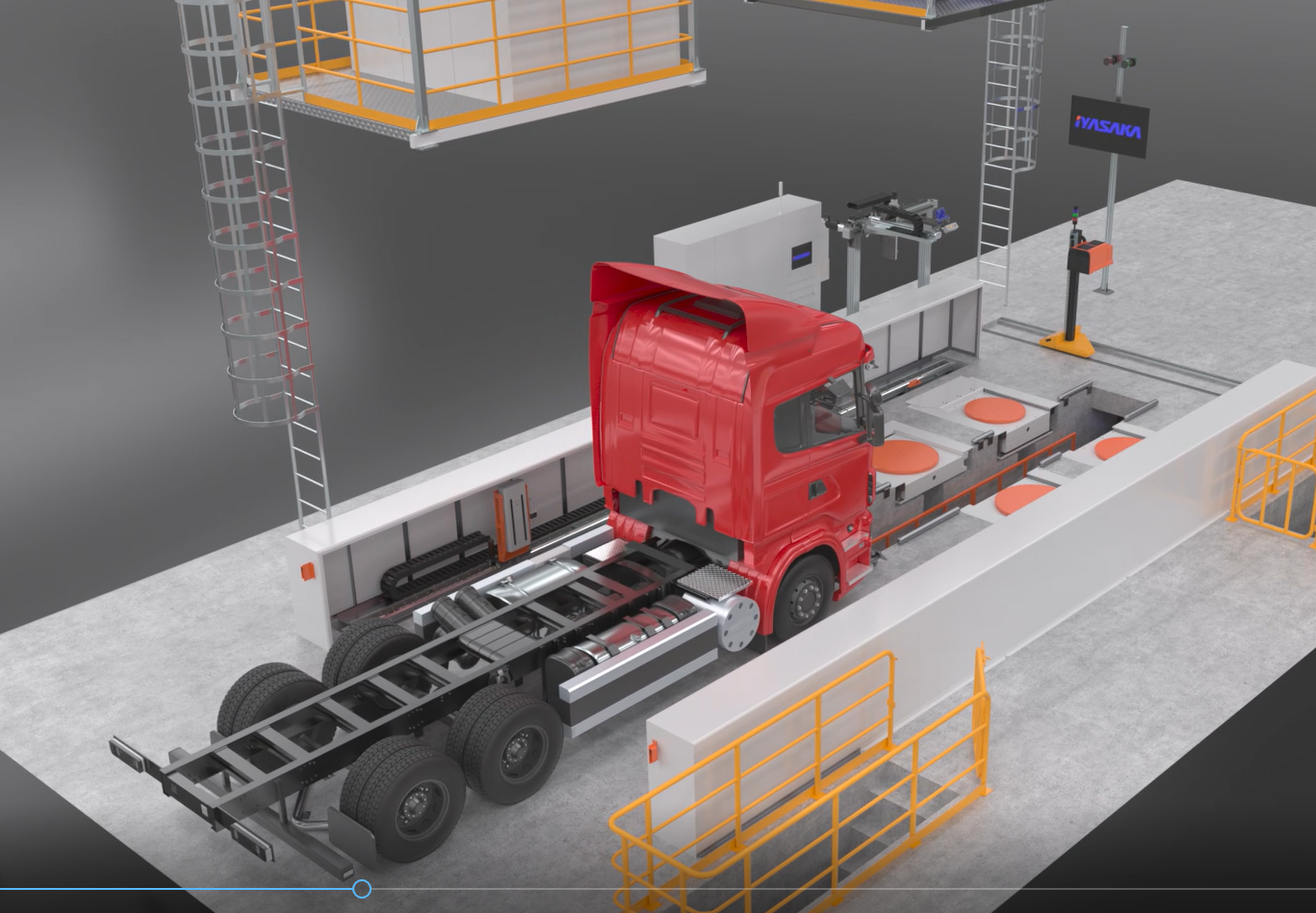
The non-contact 3D laser commercial vehicle four-wheel alignment bench is a special equipment used to measure and adjust the wheel alignment of assembled vehicles. It positions, measures and judges the wheels through the aligner to ensure that the wheel alignment meets the design parameters and requirements.
The four-wheel alignment adopts dynamic laser illumination matrix to reconstruct the tire 3D model technology and multi-line laser irradiation imaging processing technology, which has the characteristics of high measurement accuracy, small repeatability error and stable operation.
Equipped with a wireless steering wheel level, it can measure the angle of the steering wheel when it returns to zero, and feed this back to the adjustment of the toe-in value.
Measurement Content (Actual measurement content depends on vehicle model)
1. Automatically measure the individual toe-in of each front and rear axle wheel
2. Automatically measure the total toe-in of each front and rear axle wheel
3. Automatically measure the camber angle of each front and rear axle wheel
4. Automatically measure the driving direction of each front and rear axle
5. Automatically measure the chassis symmetry axis
6. Automatically measure the rear axle thrust angle
7. Automatically measure the parallelism of double front axles
8. Automatically measure the steering wheel deflection angle with a steering wheel balancer
9. Measure the toe-in runout compensation of each wheel of each front and rear axle
10. Measure the camber angle runout compensation of each wheel of each front and rear axle
11. Measure the caster angle and kingpin inclination angle of the front axle
12. Measure the maximum steering angle of the front axle (optional)
Adjustment Content (Actual adjustment content depends on vehicle model)
1. Individual toe-in of front wheels
2. Total toe-in value of front wheels
3. Parallelism of double front axles
4. Parallelism between rear axles
Testing Principle
Adopting the independently developed 3D laser sensor, multi-line laser projects on the outer surface of the tire. The binocular 3D vision sensor captures the images of the multi-line structured light on the tire surface at the same time. The 3D point cloud data of the wheel side is obtained through stereo vision algorithm processing. The toe-in and camber angle are measured by a specific evaluation and measurement algorithm, and the caster angle and kingpin inclination angle can be calculated through the swing method test.
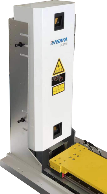
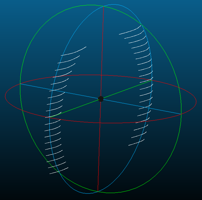
3D Laser Sensor 3D Point Cloud Data
Measurement Range and Accuracy
Item | Measurement Range | Accuracy |
Individual Wheel Toe-in | ± 10° | ± 1’ (±0.3mm/m) |
Total Wheel Toe-in | ± 10° | ± 1.5‘ (< ±0.45 mm/m) |
Wheel Camber | ± 10° | ±2’ (±0.6 mm/m) |
Driving Direction | ± 10° | ± 1’ (±0.3 mm/m) |
Rear Axle Thrust Angle | ± 5° | ± 1’ (±0.3 mm/m) |
Double Front Axle Parallelism | ± 10° | ± 1’ (±0.3 mm/m) |
Main Configuration
No. | Name | Quantity |
1 | 3D Laser Measurement Sensor | 4 pcs |
2 | Automatic Positioning System for Laser Sensor | 4 sets |
3 | Rotating Disc | 4 sets |
4 | Integral Calibration Frame | 1 set |
5 | Calibration Frame Gauge Moving Device | 1 set |
6 | Steering Wheel Level | 1 set |
7 | Steering Wheel Level Calibration Device | 1 set |
8 | PLC Electric Control Cabinet | 1 set |
9 | Industrial Control Computer | 1 set |
10 | Test Bench Display | 3 sets |
11 | Wireless Barcode Scanner | 1 set |
12 | Result Printer | 1 set |
13 | Traffic Light | 1 set |
14 | Emergency Stop Circuit | 1 set |
15 | Tire Guide | 1 set |
16 | Control System | 1 set |
Back